 The Perkin-Elmer Data Systems Terminal 1100 |
|
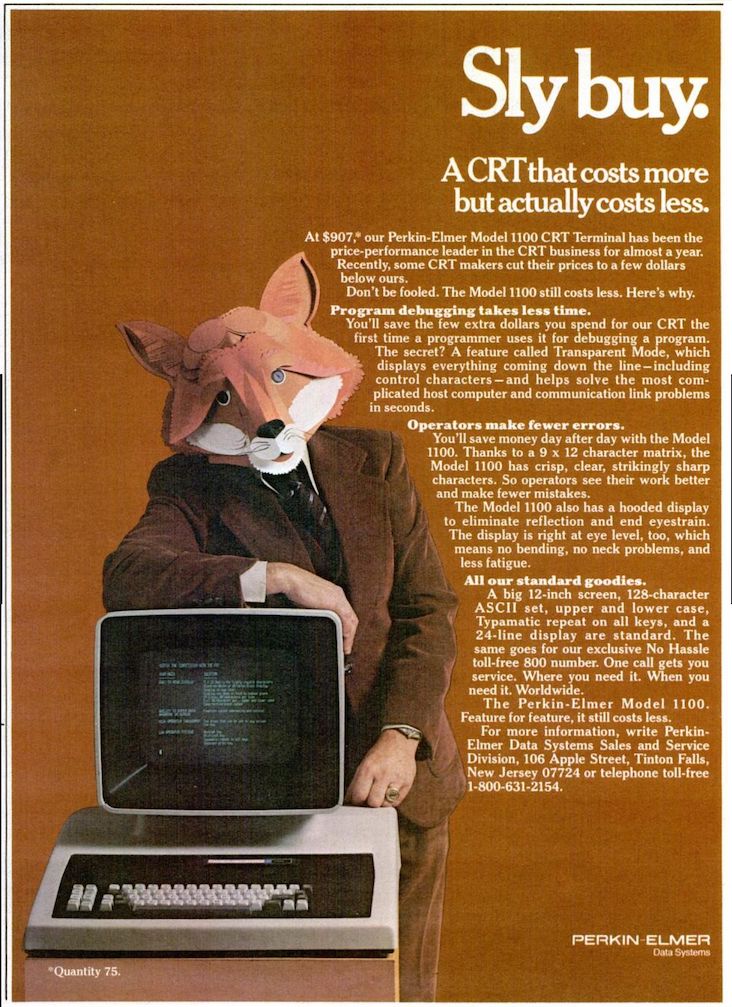
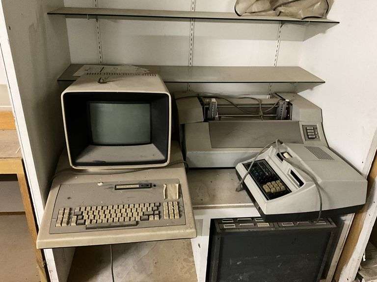
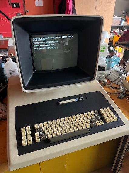
Behold, The Perkin-Elmer Data Systems 1100…aka The Fox But don’t say that too loudly, apparently P-E lost that trademark dispute. Not so for the 550 Bantam and model 1200 Owl. Add the Pussycat page printer and you’ve got a nice setup. No, I’m not joking. I first spotted this terminal in the basement of a 100-year-old department store, covered in dust and looking forgotten. Unfortunately, it wasn’t part of the auction contents at that time, but with some cajoling, the auction company agreed to include it in a round two, if ever there was one. Given the tumultuous financial situation of the building, and some sort of involvement with a tax lien, and sheriff’s sale, I was surprised when it made the online catalog a couple months later. I was all-in.
According to literature, initial deliveries were in Jan of 1977 and the unit was available for outright purchase in the amount of $1541 (or roughly $8100 in 2023). Despite that shocking number, this was considered a low-cost, affordable, terminal at the time, and was achieved by use of a microprocessor rather than banks and banks of expensive discrete IC’s. That said, it has no "computing power" in and of itself, and falls solidly into the dumb terminal category.
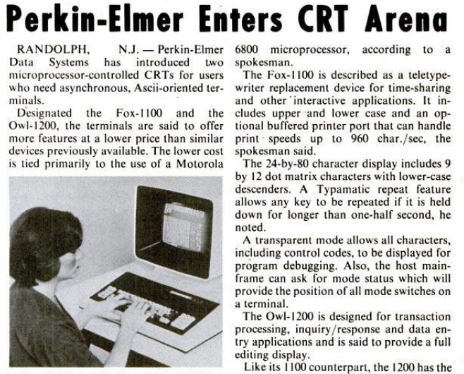
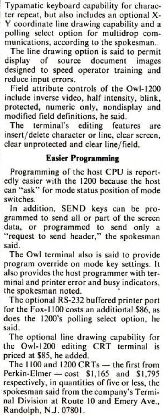
You might be surprised to learn that Perkin-Elmer is still around. They got into the computer biz by buying Interdata in 1973, and exited that sector completely by 1988. One magazine claim is that they sold over 10,000 terminal units by ’80, but you wouldn’t know it if relying purely on Google; bitsavers has some generic docs, but otherwise there’s just not much out there in terms of photos, documentation or other information.
Features:
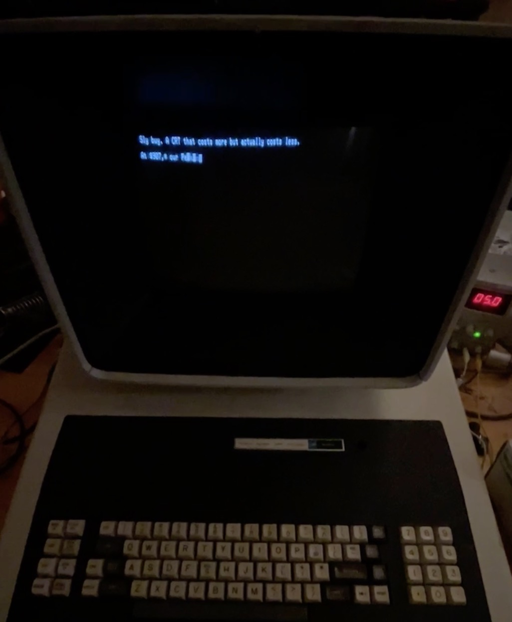
This terminal has pretty much what you’d expect for the time in features: selectable 75 to 9600 baud, half and full duplex mode, 4 parity options and a choice of 1 or 2 stop bits. Communication is RS-232 with a 3-pin(!) connector: Send/Receive/Grd. Current loop was optional as was a flashing prompt (add $15). Like older teletype machines where you snapped tabs off a plastic drum for encoding, which would transmit a “Here is” message when rotated, there’s a socket for a PROM to add your own message, executed by the Here Is KB key. Upper and Lower case it standard. Advertised is a Page Print feature. Hit the “Print” key and everything on the display would print instantly via a local printer connection…if so equipped. Incidentally, DigiKey WM1332-ND is a connector match.
Condition:
Dusty, dirty, and with sticking keys, there were no cracks or case damage present, and all keycaps were there, even if one was laying next to the unit at time of pickup(!). What I initially thought was off-white, was actually years of nicotine coupled with dust which adhered itself nicely to the keyboard and case through decades of humidity swings. Hitting the (removed) cabinet with spray degreaser, the nicotine started running down the side. Yuck. But first, an inspection of the internals was in order.
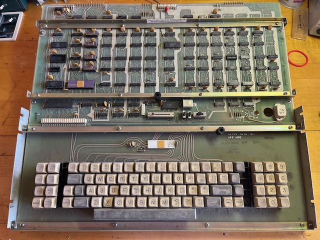
Good news there! No corrosion, no rust, no visible damage of any kind on the logic board. The monitor chassis was equally clean, if not dusty. And the CRT showed signs of life. The bottom panel was missing a peel-and-stick foot, but I found Digikey RP969-ND to be a close physical replacement, and identical in thickness. And yes, this thing has 5 feet: 2 in front and 3 across the back!
Construction: This thing is huge. Honestly, there’s no reason the 1100 needed to be this large unless P-E was trying to sell it on the bigger-is-better mentality. The fact that their other terminals are quite compact (as was the competition) is proof enough. Inside is a lot of dead space and a larger than necessary logic board. However, for being an “inexpensive” terminal, no corners were cut. By the time I finished the restoration I felt myself ‘right at home’ and really liking the design. The base is lightweight aluminum, louvered for airflow. The keyboard is on aluminum rails, the assembly dropping down and forward, secured by screws. Did I mention everything is with screws? And lock washers? And flat washers behind the lock washers?
The lower cover and black CRT trim are vacuum molded textured plastic, which was the style of the time. This makes for a lightweight setup. The CRT enclosure is a foam molded plastic with spatter paint surface, very similar to the body of an Apple II. Most everything is modular which makes service a breeze.
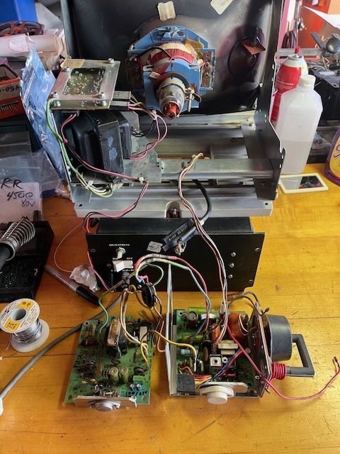
Remove 4 screws on the lower rear and the entire CRT assembly slides out the back. Remove 2 vertical screws and the CRT cover then slides rearward, exposing a compact chassis made by Motorola. In the base of the CRT pedestal is the low-voltage power supply for the logic board. And about that CRT mask…it’s secured with springs so it self-centers when the outer cover is slid on.
To remove the lower cover, there’s two screws at the front bottom corners, and two exposed screws at the rear. That’s it. Lift off and all the logic is exposed.
The Monitor Chassis:
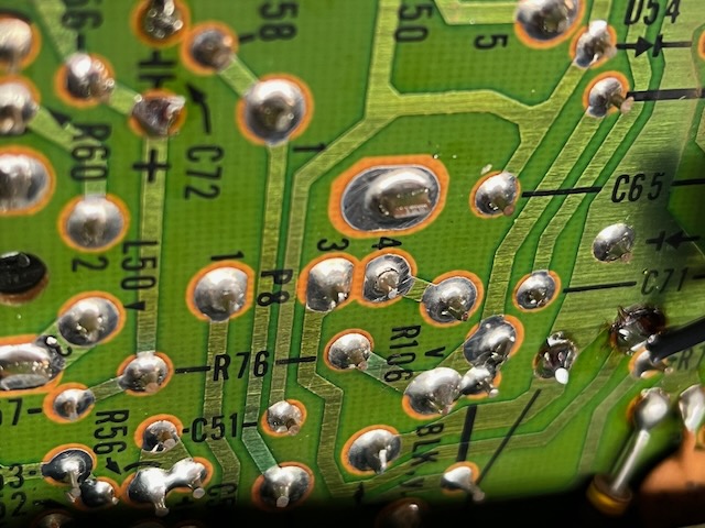
This is pretty slick, too. There’s a small AC transformer, I assume for isolation purposes, that feeds a power regulator board in the top left of the unit. It’s fused, of course (lots of fuses so far). This PCB provides ~70VDC via a wire pair to the right side of the unit. On the right side is a small board that provides vertical sweep, and an identically sized board that provides horizontal sweep. A few turns of wire around the horizontal output transformer provide filament current for the CRT; elegant. Both boards are modular and every wire has a connector or small spade. Remove a few machine screws and that twin board assembly slides out for service. Cutouts on the backside of the brackets mean you can reach 80% of the backside of the board with a soldering iron without pulling screws and wires. From a serial number tag I spotted, I believe this is a Motorola package sold to OEM’s. The CRT phosphor is white. I can find no schematics or reference on the web (no Sam’s, either).
Initial power-up had showed signs of life on the CRT, but for longevity, those old electrolytic caps would need replacement. I basically shotgunned the vertical, horizontal, and low voltage boards and then had to dig in on a thermal intermittent that turned out to be multiple cracked solder joints on the interconnects preventing the horizontal oscillator from running.
Keyboard:
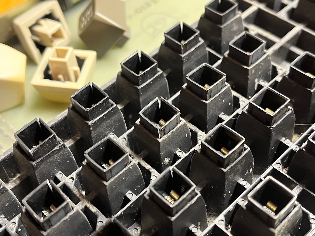
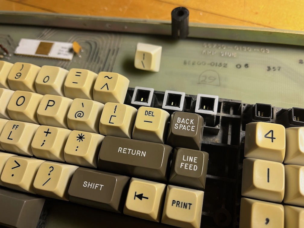
The 1100 uses a waffle-style keyboard made by Hi-Tek. Not unusual for the time, the design was reliable and cost effective, using square plastic plungers that physically separate vertical metal “fingers” for each key. When the plunger is depressed, those fingers are allowed to come together. Hi-Tek supplied HP, TI, and other popular manufacturers. But there is a defect in this design that only becomes apparent with age (see below).
Indeed, the corners of the plungers start to crack, so that when the plunger is pushed, it spreads the sidewalls and ends up jamming in the down position. Being a "waffle" design, even if I could get some replacement plungers to tackle the worst offenders, the entire assembly would need to be de-soldered as one unit, and then carefully dismantled. A rather daunting task. Even then, there was no guarantee that good used plungers would stand up to time, either.
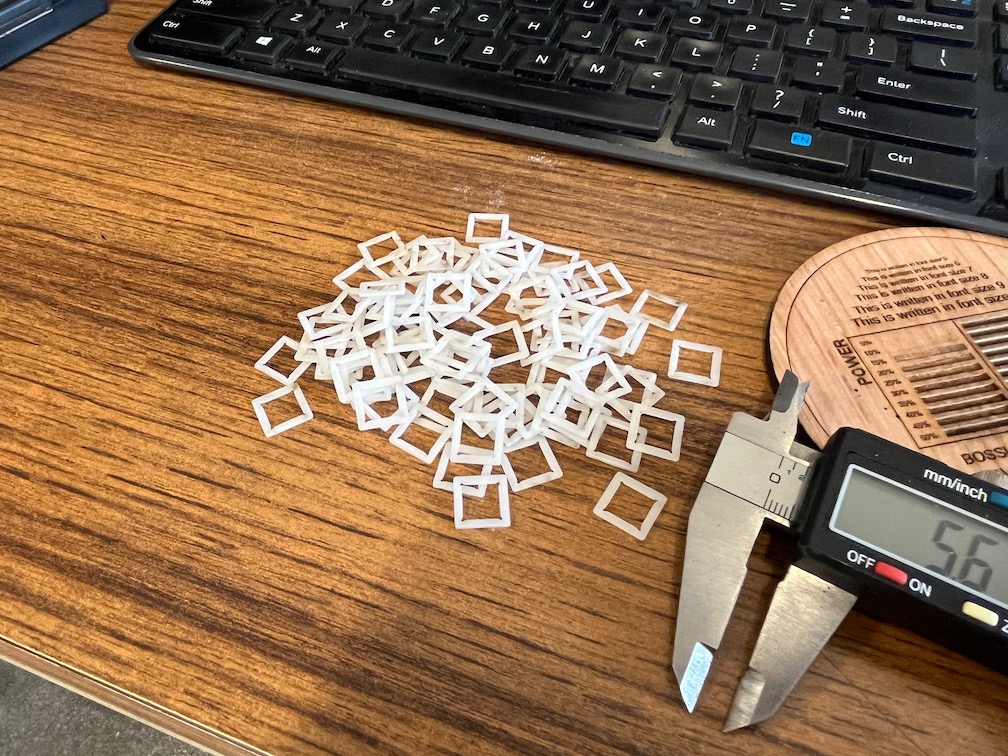
While trolling one of the keyboard forums, I found a link to an old post where someone had come up with a clever solution. Constrained Collars, for lack of a better term. When a plunger is pushed down, the fingers come together -just- before the plunger bottoms out, so you've got about 0.8 mm to work with. The square dimensions were also critical, especially since not all of these plungers were the same size (the left function keys and the right 10-key are ever so slightly different than the primary keys). 8.1 mm square seemed to be just right. After getting my hands on some 0.8 mm Acetal plastic (Grainger 55RW33), and drawing up various sizes in Inkscape, I paid a visit to the local makerspace to use their laser. After getting a good fit, I ran off several dozen and headed back for disassembly.
With all the keys removed, scrubbed clean and ready for install, I carefully fit the collars while using a knife point to keep the plungers from depressing. Then it was a matter of methodically wiggling each keycap into place and working down the line. Not only did this work functionally, it also provided a bit of positive feedback while typing that this design lacked.
Communication:
So how does one confirm everything else is in working order? RS-232, of course! Transmit, Receive, and Ground via a 3-pin Molex connector. That's it.
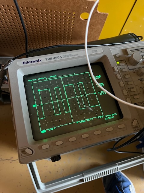
Well now, that ended up being a problem. My scope confirmed the 1100 was working as intended, but today's USB to 232 converters don't adhere to the standard which dictates both positive and negative voltage excursions greater than +/- 3v.
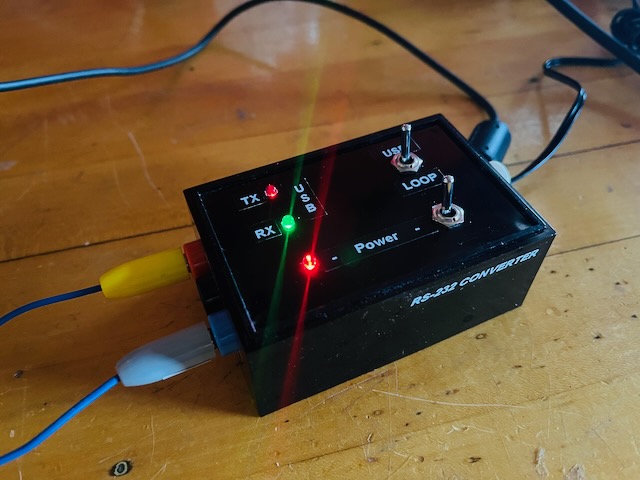
After fighting various converters and adapters, I ended up "rolling my own" using a modified MAX232 board I had laying around. With that, I could then communicate directly over USB with my laptop, make minor CRT adjustments, and test out various code sequences (note: there aren't many!).
So, with keyboard repaired, new caps installed, boards and interconnects cleaned up and cabinet restored, the 1100 restoration is complete.
Now to put it to good use!
Additional Perkin Elmer Resources:
|