Thinking about installing your own photovoltaic solar system? There’s no better time than now, especially if the fed tax break continues to stand. Prices on panels keep dropping, and if you can offset labor costs yourself, a grid-tie arrangement might just be a no-brainer.
For years I had wanted my own solar array, but I never seriously considered it, figuring it would be too expensive for the ‘average joe’. In 2015 I ran the numbers and realized it might just be feasible. It helped that I had just installed a very rudimentary 12VDC system on an outbuilding of mine to power lights and a garage door opener, so had some feel for component costs. Scaling this, I put together a plan for a DIY system. Below is the tale….
My plan was simple...
Getting Started:
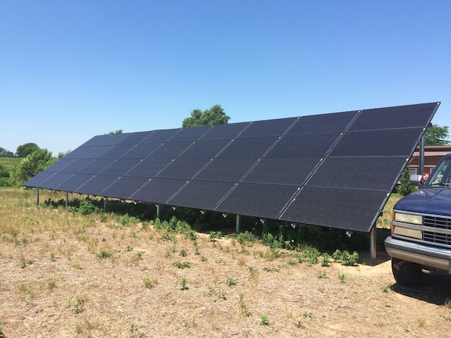
Initially I looked at solar packages and compared overall kWh, cost and technology. I already knew I wanted a ground mount system. This is snow country so I’d need to clear the panels occasionally. I’m also vehemently against unnecessary holes in roofs, especially when I’ve seen materials expand and contract over seasons. Ground mount also gives you the flexibility to optimize panel angles and to get to key parts should service be needed. The downside is code requires limiting access to the high voltage wiring on the back of the array, either with plastic netting, or with a physical fence.
If you’re limited to a roof mount, some folks have suggested getting fresh shingles (and verify roof deck integrity) before you go to the trouble and expense of covering your roof with panels. Of course a roof mount may be more difficult for a DIY’er depending on height and angle, and a roof mount requires careful study of the EL code. Many jurisdictions will dictate location, marking and number of PV disconnect devices for a roof mount for public safety (including one on the roof itself). Remember that even if a downstream inverter is shut down, as long as there’s sunlight, there’s high voltage DC present on the panel conductors. Not a good combination if firemen show up to put out a fire during the day and encounter these live circuits with no way to disable them.
How big of a system?
First thing I did was pull data from my previous years’ electric bills and throw them into excel. This gave me a picture of annual usage, peak months, year-to-year variation over several winters and to play out different scenarios once you tie this usage to cost per kilowatt hour. If payback on an 8kW system is x-years, is it worth paying y-dollars extra for a 10 or 12kw system based on my annual usage and utility cost? Things like that.
Also to state the obvious, go after the low-hanging fruit first. Find your phantom loads and eliminate them. Replace incandescent bulbs with LEDs if you can stand it. Use a kill-a-watt type device to ID “power hungry when off” equipment and add a line switch. Every watt you reduce here is one less what you’ll have to compensate for in your PV design.
I also plugged into a spreadsheet the cost of various ‘PV packages’ online to find the sweet spot of cost vs performance. Eventually this caused me to realize I should really just design my own custom system, cherry picking parts from different suppliers. Be warned that if you go this route and screw up, you have no one to blame but yourself.
System Specifications:
Ultimately, I settled on a 10kW, series-string, isolated DC system. With no concerns about shading, the cost and complexity of micro-inverters didn’t make sense. I also was planning on a single plane of panels, so I didn’t need multiple MPPT* inputs. All my strings would combine in parallel at the array.
A case can be made for having more than one inverter, in my situation, the inverter would be mounted on a wall inside my garage, and space was limited (code also dictates min and max mounting heights, so consider that) so one large unit was a better fit than two smaller units (with associated conduit/switches). I chose the SMA SunnyBoy 10000TL-US. This unit has an efficiency of 98% and is a DC-isolated design, that is, there is no transformer coupling to the AC mains. So, unlike most systems where the negative conductor from the PV panels gets grounded, both positive and negative ‘float’ with respect to ground.
Theoretically, it means no ground conductor is needed between the panels and inverter as long as there is no other metallic connection: the array is frame grounded for lightning protection, the inverter is grounded to the building, and the DC is isolated (grab either cable and stick your finger in the ground and there’s no current flow). In reality, be expected to provide heavy copper between the inverter and array to satisfy the inspector.
The panels I chose are Suniva “black” OPT285’s (285 watt rated). These are US made, have a 25 year lifetime and, well, look pretty slick. Each panel is 65” x 38.7” and weight is right around 40 pounds. Now, that may sound manageable, if a little awkward, to move and install. But consider there are 36 panels in the system (30 to a pallet, if I recall). So I was dealing with 1500 lbs of glass panels, plus shipping with a lift gate charge. Ultimately, we moved groups of panels down our ragged dirt lane, 6 at a time in the back of a pickup, each wrapped in moving blankets, dispensed from the bulk pallet packaging from a shed up at the blacktop. Since damage that results during transit must be identified before the carrier leaves, we had a couple extra bodies on hand to help quickly unwrap each panel and check the glass and aluminum frames, pulling from one pallet and re-stacking on a second.
So, why these panels?
In my opinion, designing a PV system is a careful balancing act. Screw up on any one factor and system performance will suffer. If we go back to Ohm’s law, Power = Voltage x Current, with the goal of maximizing power at all times. Sounds simple enough. Ideally, you want to saturate your inverter (oversize your array) as that’s where it operates most efficiently. So, do we focus on optimizing voltage or current? Well, not so fast.
PV cell efficiency improves as temp drops (voltage goes up). So, this ends up being one of the design constraints. Beyond a certain voltage, insulation breaks down and obviously the inverter has an input limit. Of course this means during the hot months of the year your voltage level will be well below the max.
On the other hand, if you focus on higher current at the trade off of lower voltage, you need more copper, not only to carry the current, but again to offset voltage drop. Paralleling strings also means an individual fuse or breaker is required for each, so that becomes a factor, and in an isolated DC system both the positive and negative conductors of each string are required to be fused so figure double. Can you get a combiner box to accommodate all those strings? At what cost?
To complicate matters, you now have to consider your mounting arrangement. One large panel will produce more voltage than a smaller one, but will the number required mean more or less cost in mounting hardware? More steel in the ground? Will it be a problem wrangling a huge glass panel up to the third or fourth row by yourself without scratching anything up?
All you can do is run the numbers for different scenarios. I found lots of close-out deals and ‘partial pallet’ sales at deep discounts on panels. If you’re flexible in your design, this can be a great way to save on the costliest portion of the project. I ended up with three strings of 12 panels each, and using the cut sheets, this worked out to an ‘open circuit’ voltage of 568V. That’s a good place to be as it’s under the 600V limit of many wiring devices and cables, including the THWN-2 wire I used between the combiner box and the inverter, but above the minimum inverter voltage for excitation during worst-case situations.
One other interesting fact, is that you can combine two strings in parallel at the array without needing to fuse them, but per the code, if you bring in a third string, all must be fused. Above a certain voltage level (like what we’re dealing with here), breakers aren’t practical, so you really are dealing with (expensive) fuse cartridges in DIN holders. While you can open these (when NOT under load!) for service, it’s not a legit way for the utilities or rescue personnel to shut down a system. You’ll want to get alignment between local code, the inspector and your utility company on disconnect placement.
The Work Begins:
One of the first things I did after finalizing my component BOM was to play with the PV Watts Calculator http://pvwatts.nrel.gov/ to determine the best angle and orientation for my array. Did the yearly power generated make sense? Financially was this still viable before pulling the trigger?
I also used the Ironridge engineering design guide http://www.ironridge.com to determine the footprint and column location for my array. Ironridge makes an excellent aluminum rail system that allows for fast and easy panel mounting, and they have rail connectors and top caps that let me use regular galvanized pipe that I bought locally. A little spendy, but worth it in my opinion.
Knowing array orientation, and my pipe locations, I drove a long steel rod into the ground at one of the planned corners, perfectly plumb, and used its shadow at ‘solar noon’ to mark off true North/South. From there it was simply a matter of measuring N/S from that pin to mark the second corner, then using this newly established line and the Pythagorean theorem to set the opposite corners 50 feet away. Cheap landscaping flags made quick work of marking all the post locations in between.
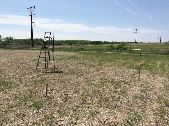
Steel rod visible next to ladder; mallet in foreground. Stake is through N/S line.
With corners located, it was a simple matter to use a string line and level to determine the max rise over run for the array to calculate how much steel pipe I'd need, and to see if it was viable to get both a short length (for the front) and a long length (for the rear) out of one standard 21' length of pipe. Over my 50' length, the ground dropped 12". It was easy enough to model the array in Google SketchUp, but graph paper and pencil would have worked just as well. Indeed, if I matched the longest 'short' corner with the shortest 'long' corner, I could get a pair out of one pipe, maintain the 30 degree array angle, account for a 4' bury depth and keep the whole thing high enough off the ground to push a mower under the front edge, and keep it all out of the snow.
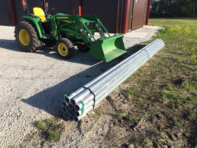
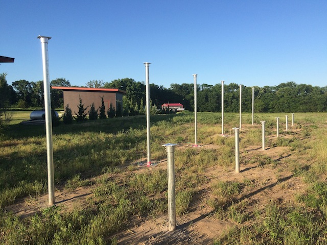
I sourced the 3" galvanized pipe (3.5" OD) from a local industrial steel provider. Steel isn't cheap, but delivery is usually built into the price.
The 21' standard lengths meant I could just barely manage these myself..usually with one end dragging in the dirt.
Here the 3E only had to handle moving a few pipes at a time; lotta weight out front.
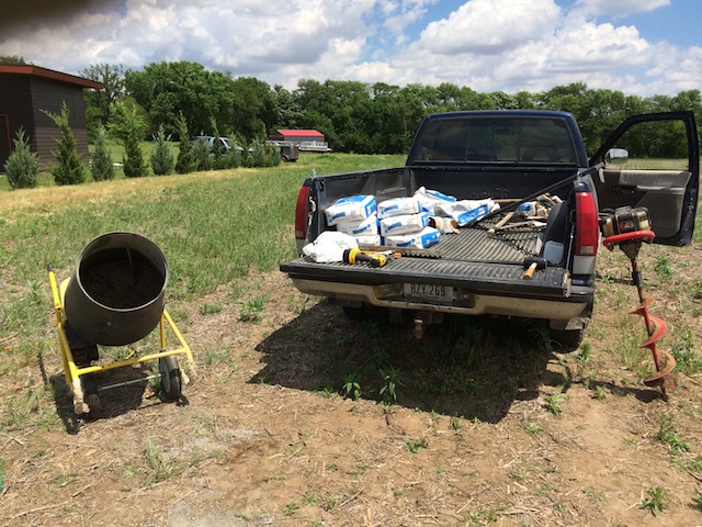
This is where having a cement mixer and post hole digger really paid off. Each 6” (or was it 8"?) hole took a bag and half of cement.
After drilling a hole, pea-gravel was poured in and compacted, then a measurement taken from the top of the rock to a string line.
Nearby, a 12" chop saw made pretty quick work of cutting the steel pipe just a little bit longer.
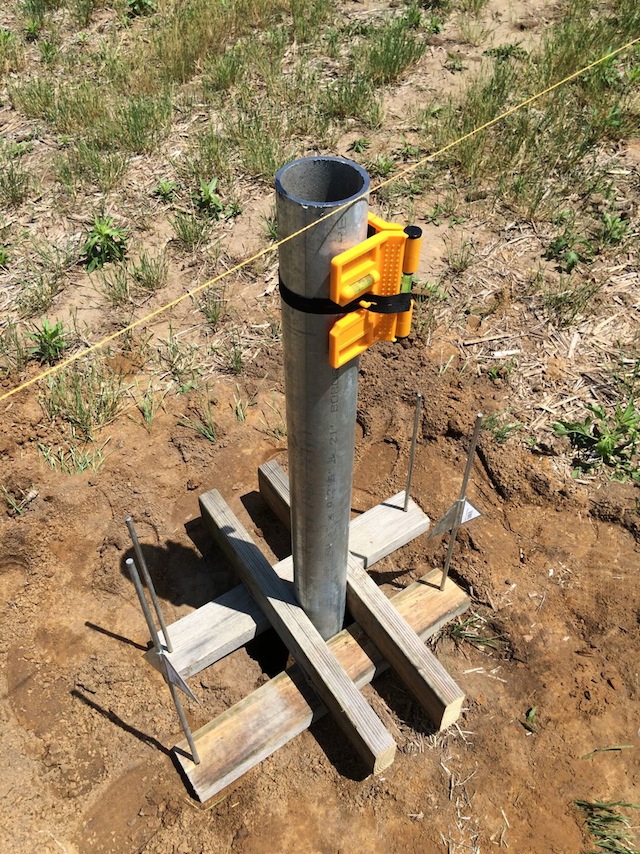
A trick swiped from the 'net. The 2x4's are screwed together and slip over the end of the pipe. Holes are pre-drilled to allow cheap electric fence posts (cut in half) to slip through. Get the pipe into position, plumb it up, then drive in the rods. A couple fixtures like this allowed for setting up multiple columns, then mixing/pouring several batches of cement at once. All columns were cut prior to install.
A pretty stout foundation for 1500 lbs of PV panels, but windload had to be considered in an open field.
Note the Ironridge caps loosely mounted.
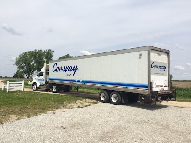
Meanwhile, the racking and PV panels were delivered.
No way the 53' trailer was making it down our dirt lane, so parts were staged and brought back to the install site via pickup truck.
And...we're off! Installation of the aluminum rails went quickly. Again, the cheap cut-off saw made quick work of cutting all the rails to length. Top and bottom panels are secured with proprietary end clamps while mid-clamps capture the edges of the intermediate panels. These are available in black or mill finish to match your panel frames. A string line and pencil was used to establish the bottom panel base line. Each row then stacks off the panel below, so it's important to take your time and get it right. Up to this point I had done all the work myself, but getting panels set beyond the first row (remember, these are over 5' long) required a second set of hands. My wife was happy to lend a hand. Panel weight wasn't too bad, but you don't want to scratch the glass or that nice aluminum.
I'm told that a solar array makes a great lightning rod, and with this 50' long target, I didn't doubt it. There are also lots of 'moving parts' in a system like this and code dictates that all those parts must be grounded. Stainless steel lugs are attached to each aluminum frame rail and allow continuous braided copper to run from one end of the array to the other before terminating at a buried copper clad grounding rod. WEEB clips get installed with all of the panel mid-clamps. These stainless clips 'bite' through the panel's anodizing to establish a gas-tight connection.
Mounting the top row of panels wasn't terrible, but it did require some forethought. After the first and second row were complete, I used the bed of the truck as a platform to stage the top panel into position (edge resting over the rail tops). Then I could pop up on a ladder in the open 3rd row position, lift the panel and slide it down into place, careful to get the clamps lined up. Then pop up in the now open 4th row spot, reach down and tighten the clamps. Hop back into the truck bed, place the 4th row panel and secure it. Remember, all those mid-clamps will require torquing one way or another.
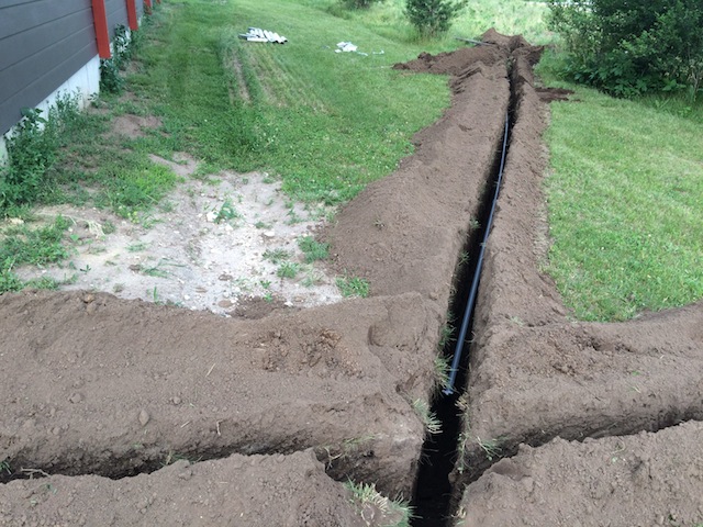
I wanted my install to be as stealth as possible since the building has no other exterior boxes, conduits, or even a meter base. The service feed from a yard pedestal is underground, and I had made provisions years ago when pouring the building's foundation for multiple 3" PVC pass-throughs that come up through the cement floor just inside the building. I rented a trencher for a day and zig-zagged my way from the pass-through near my main panel, over to the array, keeping overall distance to a minimum. The DC conductors are in continuous conduit, and getting this matched and glued up along with pulling the conductors was a real pain in the ass. Backfilling by hand as a storm approached, more so.
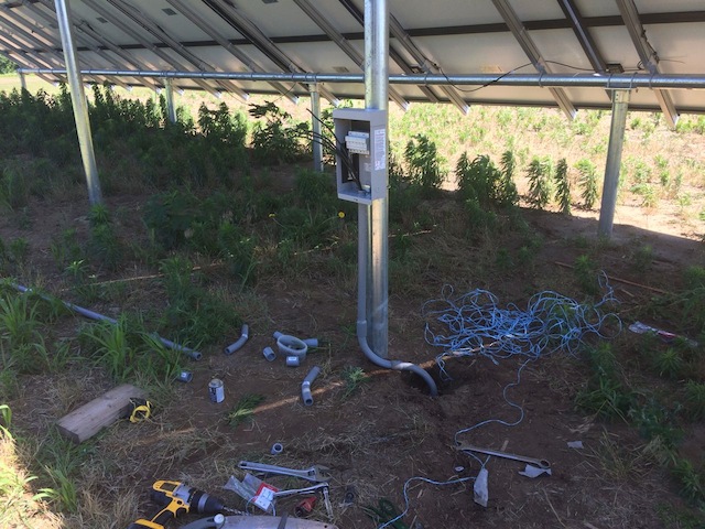
My combiner box is a Midnite Solar model, outfitted with 6 DIN fuse holders (one pair per string). In fact, the busbars, the fuses, the DIN holders and the box itself all came from different ebay sellers! This photo was taken June 26th and you can see the weeds popping up. About prime-solar-time to get this system online.
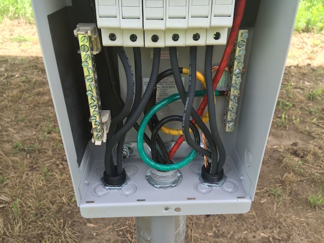
Wiring in the combiner box. DC conductors to the inverter are 6 AWG THWN-2, relatively cheap and available at the big box store. The yellow flagged wire coiled in the back is a spare. The flexible wires to the fuse holders are PV type, rated against UV and having a higher voltage insulation (1kv). The majority of panels on the market are equipped with flying leads that are terminated in MC4 connectors but because crimpers for these are few and far between, it's much cheaper to buy pre-made PV wire lengths with these connectors already in place, and simply cut the wire to the length you need.
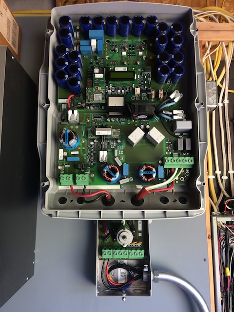
On the other end of the DC conductors is the inverter. The SMA 10000TL has an integrated disconnect switch rated to open under load; AC wiring to the main panel comes into this same box. Since the disconnect is within 5' of the conductors entering the building, an outside disconnect is not required at point of entry. However, I do have an AC disconnect at my electric meter, and by regulation, disconnecting AC will force immediate shutdown of the inverter to prevent back-feeding. Just as with conventional AC wiring, conduits have to be sized for conductor gauge and fill.
This is a good time to talk about main breaker sizing. My existing Square D panel had a 200A main breaker, and if you add up the load breakers in your panel, you'll probably easily exceed this number. Now obviously John Q Public doesn't normally exceed a 200 amp draw at any given instant, but because you now have a second source of power feeding into the panel, you conceivably could draw more amps than the busbars were designed for. So, the NEC requires derating the primary breaker to a value, that combined with the PV source, does not exceed 120% of the bus bar rating. If you've shopped for such a breaker, you'll know a) they're stupid expensive, and b) the listed ratings have fairly large steps. In my case de-rating to 175A was adequate.
With regards to the AC breaker back-feeding the panel, this should be placed at the opposite end of the busbars from the primary breaker to avoid hot-spotting, and its rating will be based on 125% of Imax where Imax equals max string current x number of strings.
Before breaking ground, all of these details had to be shared with the utility company and the Office of the State Fire Marshal Electrical Bureau. If they're on top of their game, they'll even have ready-made forms for you to complete to help standardize the process.
Hey look! Even more weeds! Good news is that we're now online and generating by this point (Live: July 14, 2016). The final inspection went well, though a few additional labels were needed. Here's an example of what may be required, all dependent on your physical install. Don't be surprised if an inspector pulls out this identical 'cheat sheet'.
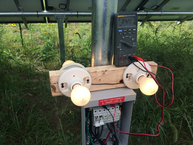
What's going on here is a check to see if each string is balanced. The 4 bulbs provide a load on the string since the inverter disconnect is open and the DC voltage is measured and compared to the other strings (422V here). This is important because one defective panel in a string (or one shaded panel) will kill that entire series. (The pic is a little misleading as only one set of fuses would be closed when reading voltage) If I did have a significant drop, I'd then need to go panel by panel in that string and measure voltage drop to find the culprit. Thankfully, that's not the case.
*MPPT: Maximum Power Point Tracking. As mentioned earlier, there are inverters available with multiple MPPT inputs. These effectively maximize the power generated on each input, so you can take advantage of multiple strings in different orientations without reducing performance of a high performing (at that moment) string.
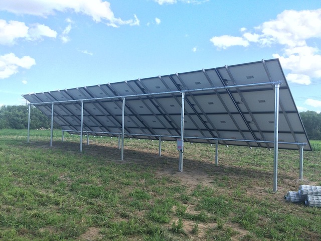
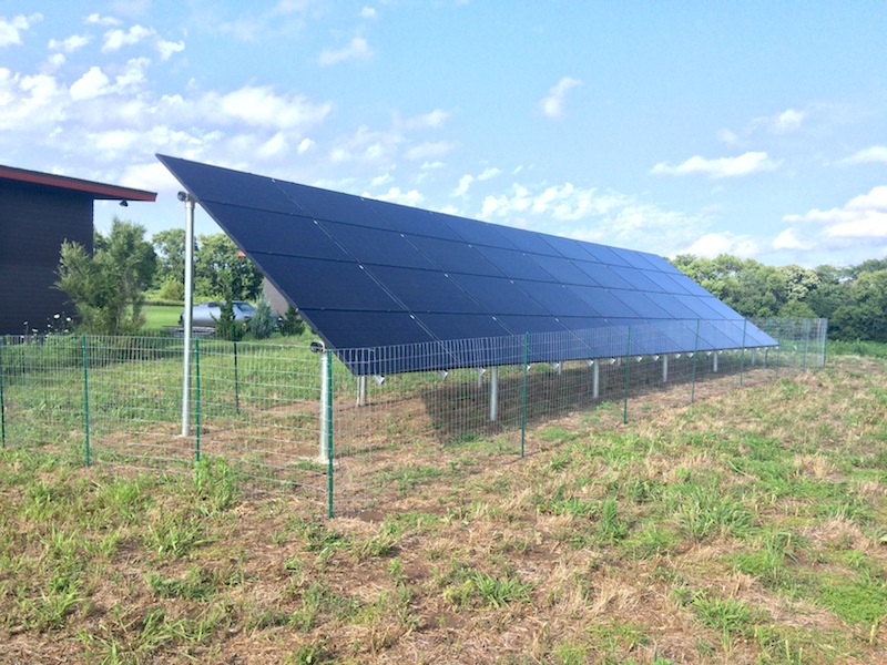
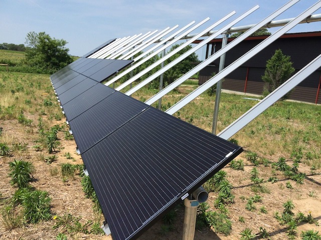
And finally, the back of the completed array. All the PV wiring carefully coiled and secured, and fencing ready for install in the bottom right of the pic. A fence you say? Well, the NEC says. Actually, the NEC says: 690.31(A) "where PV source and output circuits operating at max system voltages greater than 30v are installed in readily accessible locations, circuit conductors shall be guarded or installed in a raceway".
However, the majority (all?) of panels on the market have pigtails with MC4 connectors and no provision for conduit or raceway connections. So conceivably, someone could come by with a pair of scissors and cut through one of these wires and receive a shock (except this is a transformerless system, so..no). In some jurisdictions, plastic webbing like snow fencing, attached directly to the back of the panel is sufficient protection. Yet now you've got a nice home for birds and insects to enjoy your wiring. The other option is a physical barrier like a fence if it's acceptable to your AHJ. In the end this was preferable to webbing and potential conductor damage.
Would I do it again?
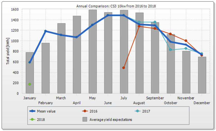
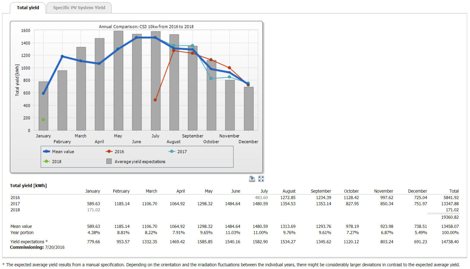
Absolutely. First year performance was surprisingly on-par with the PV-Watts estimate. Having paid a little extra for the SMA ethernet connectivity board, my inverter is online. Not only can I check to make sure the system is generating, but data is uploaded to the Sunnyportal server each night, allowing review of past performance. Now that it's January 2018, we have a complete year under our belt. In those 12 months, we generated 13.35 MWH and reduced our electric bill by over $1000 annually.
If you're considering a grid-tie arrangement, be sure to get your PoCo's rates and regs in writing. Our local utility buys power generated at the same cost as it sells it, though you don't get credit for the surcharge fees and the meter fee is slightly higher. In theory we'd get a check each month that we generate more power than we use, but since we also have other services with the same utility, the difference is credited against those charges. Other utility providers may only offset your usage and credit you nothing more. Still others operate on a revolving kWh credit basis like some cell phone plans..use it or lose it! So do your research and get it in writing.
At the time of installation (2016), the Fed was offering a 30% tax credit (Form 5695) against materials and installation cost of a PV system, with the state of IA offering additional credit. Through careful shopping and performing all labor ourselves, this brought the final system cost to just over 4-figures. At the current rate, that puts payback at under 10 years. Pretty good for PV.
Performance as of 5 Jan, 2018 - click here for details
Useful Links
Real-Time Performance of our System
PV Watts – Extremely useful calculator for determining estimated power generation at a given location.
Bruce Roe’s Energy Conservation – A friend’s collection of PV-related projects with photos.
SolarPanelTalk – A forum dedicated to PV discussions.
Renvu Solar – Aggressively priced PV components. My first stop for most of this project.
Wholesale Solar - Complete packages and components with excellent customer service
ML Solar – One of the ‘big 3’ online solar retailers and a good source for PV wire and smaller parts.
Cory Heisterkamp 2018